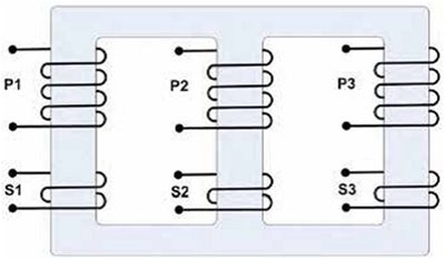
3 Phase Electrical Power Isolation Transformer
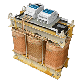
A 3 phase transformer, there is a three-legged iron core as shown below. Each leg has a respective primary and secondary winding. Thus a 3 phase isolation transformers is a 3 phase transformer which has isolated primary and secondary windings to allow the power input to be isolated from the power output.
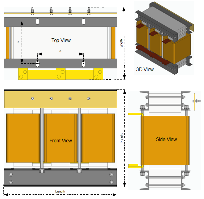
Standard 3 Phase Isolation Transformers
3 phase isolation transformers have 3 primary and 3 secondary windings that are physically separated from each other. Sometimes these isolation transformers are referred to as "insulated". This is because the windings are insulated from each other. In a 3 phase isolation transformer the output windings will be isolated, or floating from earth ground unless bonded at the time of installation.
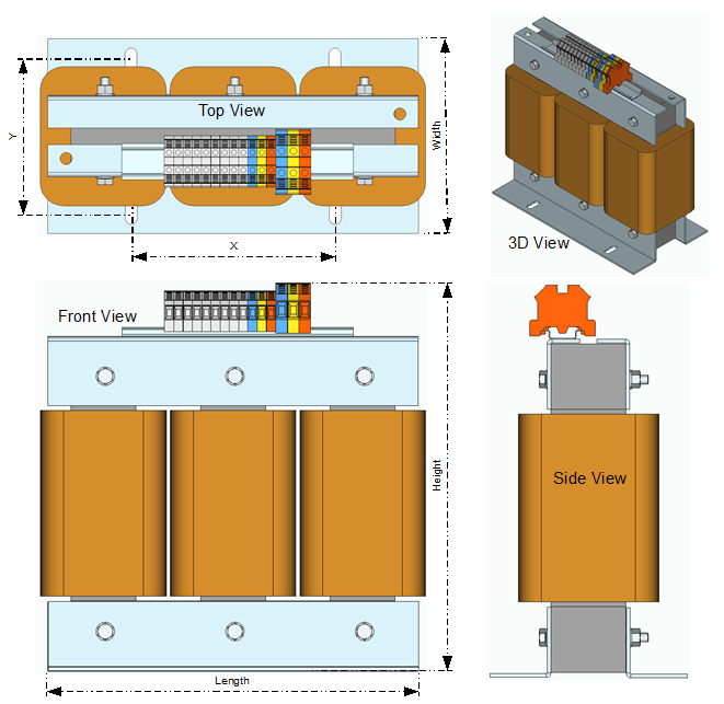
General Purpose Isolation transformers
General Purpose Isolation transformers are used to lower distribution voltages (up to 750V) to lower voltages for power distribution within commercial or industrial buildings. These “two windings” transformers provide the electrical isolation required, and allow for short runs of high current, low voltage cables, reducing losses in the system, and reducing costs.
General Purpose Isolation transformer are suitable for supplying the following type of loads
- General purpose lighting & electrical
- Motors (without VFD controllers)
- Resistive Heating
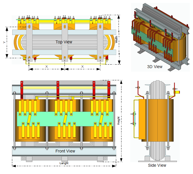
Drive Isolation Transformers
Drive Isolation Transformers are designed for supplying power to SCR (Silicon Control Rectifier) motor drives which provide convenient variable speed motor control and can save on energy.
A Drive Isolation Transformer (DIT) is designed specifically to supply power to VFDs. The isolation between the primary and secondary provides electrical isolation between the supply and the load. The transformer core is designed to handle the harmonic voltage without saturating, and the coils are braced to handle the mechanical forces that are introduced due to these harmonic currents. The coils are also designed to mitigate the impact of the harmonic currents. The winding conductors are selected and designed to keep eddy and stray losses to a minimum and the sufficient cooling is provided to dissipate the additional heat generated by the harmonic current.