Power Transformers

3phase power transformers

3 Phase Electrical Power Isolation Transformer

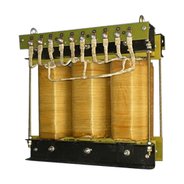
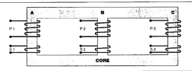
A 3 phase transformer, there is a three-legged iron core as shown below. Each leg has a respective primary and secondary winding. Thus a 3 phase isolation transformers is a 3 phase transformer which has isolated primary and secondary windings to allow the power input to be isolated from the power output.

Transformer

Standard 3 Phase Isolation Transformers

3 phase isolation transformers have 3 primary and 3 secondary windings that are physically separated from each other. Sometimes these isolation transformers are referred to as "insulated". This is because the windings are insulated from each other.

In a 3 phase isolation transformer the output windings will be isolated, or floating from earth ground unless bonded at the time of installation.

3 Phase Transformers Overview

3 phase transformers are used throughout industry to change values of 3 phase voltage and current. Since 3 phase power is the most common way in which power is produced, transmitted, an used, an understanding of how 3 phase transformer connections are made is essential. In this section it will discuss different types of 3 phase transformers connections, and present examples of how values of voltage and current for these connections are computed.

3 phase Transformer Construction:

A 3 phase transformer is constructed by winding three single phase transformers on a single core. These transformers are put into an enclosure which is then filled with dielectric oil. The dielectric oil performs several functions. Since it is a dielectric, a nonconductor of electricity, it provides electrical insulation between the windings and the case. It is also used to help provide cooling and to prevent the formation of moisture, which can deteriorate the winding insulation.

power-transformers

Applications

To supply electrical consumers of all kinds, e.g. measuring and control instruments, power electronic modules, etc.. Customized specification and dimensions ensureoptimal application.

Specification

  • Output range

    250 VA – 1000 kVA

  • Input voltage max.

    750 V

  • Output voltage max.

    750 V

  • Output current at max.

    65 A

  • Screw terminals max.

    135 A

  • Studs max.

    450 A

  • Flat termination max.

    1500 A

  • Frequency

    50-60 Hz

  • Vector group

    DYN11

  • Protection index

    IP 00

  • Insulation class

    B/F

  • Ambient temperature max.

    40° C

Construction

  • Open construction (IP 00, incorporation up to max. IP 23)
  • Separated winding
  • Resting on U sections
  • Connections to safe-to-touch screw terminals in accordance with CE (higher current ratings to studs or flat termination with bolt & shrouding)
  • High-grade, vacuum-pressure impregnation in polyester impregnating resin
  • Special versions available on request up to 1000KVA

Applicable standards

IS 2026, IS 11171, IS 12012

power-transformers-graph
KVA HEIGHT WIDTH DEPTH X Y SLOT WEIGHT Figure
0.5 200 180 125 160 90 8X20 11 A
0.75 240 240 121 160 75 8X20 13 A
1 240 240 120 160 75 8X20 14 A
1.25 240 240 135 160 90 8X20 19 A
1.5 240 240 145 160 100 8X20 21 A
2 300 300 150 180 90 10X25 26 A
2.5 300 300 160 180 100 10X25 30 A
3 300 300 170 180 110 10X25 34 A
4 300 300 180 180 120 10X25 41 A
5 360 360 200 200 135 13X28 53 A
6 360 360 210 200 145 13X28 61 A
7.5 360 360 210 200 145 13X28 65 A
10 360 360 215 200 150 13X28 72 A
12.5 360 360 215 200 150 13X28 83 A
16 420 420 250 220 170 13X28 110 A
20 420 420 260 220 180 13X28 127 A
25 460 480 285 220 200 13X28 161 A
30 520 520 315 220 200 13X28 201 A
35 520 520 315 220 205 13X28 222 A
40 520 520 320 220 210 13X28 232 A
45 580 560 335 220 205 13X28 261 A
50 505 840 500 250 265 15x35 260 B
60 505 860 500 250 270 15x35 285 B
75 550 875 500 250 265 15x35 329 B
100 560 900 520 250 270 15x35 384 B
125 595 960 550 250 280 15x35 483 B
150 635 1010 570 250 290 15x35 548 B